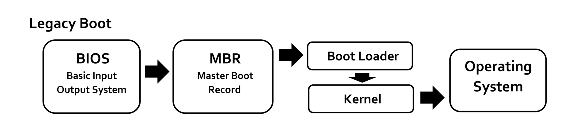
Build your own bootloader for x86 OS: BIOS (Legacy)
Bootloader is a piece of code that is executed once the system is booted. Let see how we use BIOS to load our bootloader and boot system.
1. Fundamental concepts
1.1. POST
When a computer is switched on or reset, it runs through a series of diagnostics called POST - Power-On Self-Test. It makes sure all hardware components are working properly. And finally locates a bootable device, such as a Floppy Disk, CD-ROM or a Hard disk in the order that the firmware is configured to.
POST routines are part of a computer’s pre-boot sequence. If they complete successfully, the bootstrap loader code is invoked to load an OS.
In IBM PIC compatible computers, the main duties of POST are handled by the BIOS/UEFI.
The principal duties of the main BIOS during POST include:
- Verify CPU registers.
- Verify the integrity of the BIOS code itself.
- Verify some basic components like DMA, timer, interrupt controller.
- Initialize, size, and verify system main memory (check corruptions).
- Initialize BIOS.
- Pass control to other specialized extension BIOSes (if installed).
- Identify, organize, and select which devices are available for booting.
In later BIOS versions, POST will also:
- Initialize chipset.
- Discover, initialize, and catalog all system buses and devices.
- Provide a User Interface for system’s configuration.
- Construct whatever system environment is required by the target OS.
Once BIOS finds the boot sector it loads the image in memory and execute it. If a valid boot sector is not found, BIOS check for next drive in boot sequence until it find valid boot sector. If BIOS fails to get valid boot sector, generally it stops the execution and gives an error message “Disk boot failure”.
It is boot sectors responsibility to load the operating system in memory and execute it.
1.2. BIOS
BIOS (Basic Input/Output System) was created to offer generalized low-level services to early PC system programmers. The basic aims:
- To hide (as much as possible) variations in PC models and hardware from the OS and applications. -> Try to abstract, de-couple upper layers like OS and apps from hardwares, PC models. So OS and apps development be more easier (Because the BIOS services handled most of the hardware level interface).
1.2.1. BIOS Services
These BIOS services are still used (especially during boot-up), and are often named BIOS functions. In real mode, they can easily accessed through Software Interrupts, using Assembly language.
Generally, you can access a BIOS function by setting the AH CPU register (or AX or EAX) to a particular value, and then do an INT opcode. The value in AH, combined with the particular interrupt number selected requests a specific BIOS function. (Another CPU registers hold any arguments to the function, and often the return values.)
For example: INT 0x13 with AH=0 is a BIOS function that resets hard disks or floppy disk.
Some common BIOS services:
INT 0x10, AH = 1– set the cursor.INT 0x10, AH = 3– cursor position.INT 0x10, AH = 0xE– display char.INT 0x10, AH = 0x13– display string.
ATA using BIOS (Disk access using BIOS INT 0x13)
INT 0x13, AH = 0x2– read floppy/hard disk in CHS mode.INT 0x13, AH = 0x3– write floppy/hard disk in CHS mode.INT 0x13, AH = 0x42– read hard disk in LBA mode.INT 0x13, AH = 0x43– write hard disk in LBA mode.
Memory detection
INT 0x12– get low memory size.INT 0x15, EAX = 0xE820– get complete memory map.INT 0x15, AX = 0xE801– get contiguous memory size.
Each BIOS function has a specific set of “result” registers. For errors handling, almost always set the carry flag (
JC), sometimes returnAH = 0x86(Unsupported),AH = 0x80(Invalid Command).
In Protected Mode and Long Mode, almost BIOS services become unavailable.
1.2.2. BIOS (Legacy) and UEFI
In this topic, we’ll talk about BIOS, but let see some main differences between BIOS and UEFI.
1
2
3
4
5
6
7
8
9
10
11
12
13
14
15
16
17
18
19
20
|            |          BIOS             |             UEFI             |
|------------|---------------------------|------------------------------|
|Release Date| 1981                      | 2002. Intel developed to     |
|            |                           | replace legacy BIOS arch.    |
|------------|---------------------------|------------------------------|
|    User    | Text-based.               | GUI, mouse, keyboard.        |
|  Interface |                           |                              |
|------------|---------------------------|------------------------------|
| Operating  | 16-bit, limited to 1MB of | 32-bit, 64-bit, networking   |
|    Mode    | addressable space.        | booting, remote diagnostics. |
|------------|---------------------------|------------------------------|
| Partition  | MBR (Master Boot Record), | GPT (GUID Partition Table),  |
|  Support   | up to 2TB.                | over 2TB.                    |
|------------|---------------------------|------------------------------|
|  Security  | Basic, no inherent        | Support Secure boot, prevent |
|            | security feature.         | unauthorized OS.             |
|------------|---------------------------|------------------------------|
|Performance | Slower boot times, limited| Faster boot times, optimized |
|            | hardware support          | for modern hardware.         |
|------------|---------------------------|------------------------------|
It seems UEFI more powerful than BIOS, but BIOS is still widely used because offering simplicity and compatibility with older hardware and OSes.
1.3. Master Boot Record
A master boot record (MBR) is a type of boot sector in the first few blocks of partitioned computer mass storage devices (hard disk, etc.). The MBR contains:
- Information on how the disc’s sectors are divided into partitions, each partition notionally containing a file system.
- Executable code to function as a loader for the installed OS - usually by passing control over to the loader’s second stage.
The MBR code is usually referred to as a bootloader.
1.3.1. Why is BIOS supported partition limited to 2TB?
The organization of the partition table in MBR limits the maximum addressable storage space of a partitioned disk to 2 TiB (2^32 * 512 bytes). Approaches to slightly raise this limit utilizing 32-bit arithmetic or 4096-byte sectors are not officially supported. Therefore, the MBR-based partition scheme is in the process of being superseded by the GUID Partition Table (GPT) scheme in new computers. A GPT can co-exist with an MBR in order to provide some limited form of backward compatibility for older systems.
2. Boot Process
2.1. System startup
2.1.1. Where is BIOS firmware stored?
Originally, BIOS firmware was stored in a ROM chip on the PC motherboard. In later computer systems the BIOS contents are stored on Flash Memory (or NVRAM) so it can be rewritten without removing the chip from mother board.
2.1.2. How does BIOS start running?
Early Intel processors started at physical address 000FFFF0h. Systems with later processors provide logic to start running the BIOS from the system ROM.
- Cold boot: system has been powered up or the reset button was pressed.
- Warm boot: Ctrl + Alt + Delete was pressed.
If the system has a cool boot, the full POST is run. Otherwise, a special flag value stored in Nonvolatile BIOS memory tested by the BIOS allows bypass of the lengthy POST and memory detection.
2.2. BIOS loads MBR
After POST, the BIOS calls INT 0x19 to start booting processing. When INT 0x19 is called, the BIOS attempts to locate the boot loader software (Master Boot Record) on a boot device such as a hard disk, a floppy disk, CD or DVD. It loads and executes the first boot software it finds, giving the control to it.
The BIOS uses the boot devices set in the Nonvolatile BIOS memory. It checks each device in order to see if it is bootable by attempting to load the first sector (boot sector). If the sector cannot be read, the BIOS proceeds to the next device. If the sector is read successfully, BIOS checks for the boot sector signature 0x55AA in the end of sector.
The boot signature number
0x55AAis also called magic number. It’s in the last 2 bytes of boot sector.
When a bootable device is found, the BIOS load the boot sector into memory at 0x0000:0x7c00. Execution is then transferred to the freshly loaded boot record. On a floppy disk, all 512 bytes of the boot record may contain executable code. On a hard drive, the MBR holds executable code at offset 0x0000 - 0x01BD, followed by table entries for the four primary partitions, using sixteen bytes per entry (0x01BE - 0x01FD), and the the two byte signature (0x01FE - 0x01FF).
A MBR memory layout:
1
2
3
4
5
6
7
8
9
10
11
12
13
 ___________________________
| 446 bytes execution code  | 0x0000
|                           |
|     boot loader code      |
|                           |
|                           |
|___________________________| 0x01BD
|      64-bytes primary     | 0x01BE
|  partition table entries  |
|                           |
|___________________________| 0x01FD
|   2-bytes MBR signature   | 0x01FE
|___________________________| 0x01FF
2.2.1. Boot environment
The environment for the boot program:
- CPU is in real mode.
- General purpose and segment registers are undefined, except
SS,SP,CSandDL. CS:IPalways points to physical address0x07C00. That means CPU will alway start execution your boot loader from this address. Because boot programs are always loaded at this fixed address, there is no need for a boot program to be relocatable.DLcontain the drive number, as used withINT 13H, of the boot device.SS:SPpoints to a valid stack that is presumably large enough to support hardware interrupts, but otherwiseSSandSPare undefined. The boot program must set up its own stack because the size of the stack set up by BIOS is unknown and its location is likewise variable. You can read, but the more easier way is setup new location yourself.- All BIOS services are available, and the memory below address
0x00400contains the Interrupt Vector Table.
2.3. Bootloader load the kernel
The bootloader ultimately has to bring the kernel (and all the kernel needs to bootstrap) in memory, switch to an environment that the kernel will like and then transfer control to the kernel.
2.3.1. How does Bootloader load the kernel?
If we boot from a hard drive, we have only 446 bytes available for your boot record. The todo list before the kernel can run is not much:
- Determine which partition to boot from.
- Determine where your kernel is located on the boot partition.
- Load the kernel image into memory.
- Enable Protected mode.
- Preparing the runtime environment for the kernel.
But it’s hard to finish all the list task with only 446 bytes. Other problem is there are somethings you can not do with C: Manipulate segment selectors, stack pointer, loading GDT also require special opcodes which are not available within C. (You can implement Inline Assembly).
There are several approaches:
- Geek loading: Squeeze everything from the list into the boot record. This is next to impossible, and no-space for error handling, etc.
- One-stage loading: Write a stub program for making the switch, and link that in front of your kernel image. Boot record loads kernel image (below the 1mb memory mark, because that’s the upper limit of real mode), jump into the stub, stub makes the switch to Protected mode and runtime preparations, jumps into kernel proper.
- Two-stage loading: Write a separate stub program which is loaded below the 1MB memory mark, and does everything in the list.
2.3.2. Where will you load your kernel?
You’ll have to decide where in memory you are going to load your kernel. In real mode, the easiest is to stay below the 1MB barrier, which means you have 512 bytes of memory to load things. You may wish the kernel to be loaded at a well-known position, say 0x10000 physical (es=0x1000, bx=0 when calling INT 13H).
If your kernel is bigger (or is expecting to grow bigger) than this, you should prefer to have the kernel above the 1MB barrier, which means you need to activate A20 gate (You have more 4 bits for addressing: 2^20) and switch to Unreal mode to load the kernel.
2.3.3. How do I actually load bytes?
BIOS interrupt 13H. To read from the hard drive, you probably want int 13h, ah=0x42, drive number 0x80 that uses simple LBA addressing.
3. Rolling your bootloader
Now, we already have the todo list have to do. Our approach will be Two-stage loading. Because we don’t focus on kernel development, so our kernel should be small than 512 KB and make sure we don’t exceed 1MB barrier.
3.1. MBR implementation
In 512 bytes of MBR we clear segment registers, setup SP and load the second-stage bootloader from disk. We spend 5 sectors for storing the second-stage bootloader on the disk and we load it into 0x7E00 in physical memory. This is done by using BIOS the 13H service. We setup registers to using 0x42 extended (Extended Read Sectors From Drive by LBA mode), for dl, it already hold the drive number (that is set by BIOS before transferring control to us). Finally, we jump to 0x7E00 to pass the control to the second-stage bootloader. Here is our MBR implementation boot.asm:
1
2
3
4
5
6
7
8
9
10
11
12
13
14
15
16
17
18
19
20
21
22
23
24
25
26
27
28
29
30
31
32
33
34
35
36
37
38
39
40
41
42
43
44
45
46
47
48
49
50
51
52
53
54
55
56
57
58
59
60
61
62
63
64
65
66
67
68
69
70
71
72
73
74
75
76
77
78
79
80
[BITS 16]
[ORG 0x7C00]

jmp short Start
nop

; TODO: Setup BIOS Parameters Block here.

Start:
    ; 1. Clear segment registers.
    xor ax, ax
    mov ds, ax
    mov es, ax
    mov ss, ax

    ; 2. Set up SP starting at address 0x7C00 and grows downwards.
    mov sp, 0x7C00

    ; 3. Load the second-stage loader.
LoadLoader:
    mov si, ReadPacket          ; Load the packet address to si.
    mov word[si], 0x10          ; Packet size is 16 bytes.
    mov word[si + 2], 0x05      ; We we load 5 sectors which is enough space
                                ; for our second-stage loader.
    mov word[si + 4], 0x7E00    ; Offset which we want to read loader file.
    mov word[si + 6], 0x00      ; Segment, the logical memory to load the file
                                ; is: 0x00 * 0x10 + 0x7E00 = 0x7E00
    mov dword[si + 8], 0x01     ; 32 bit low address of LBA.
    mov dword[si + 12], 0x00    ; 32 bit high address of LBA.
                                ; We will start at sector 2 but set 1 to LBA
                                ; Because the LBA is zero-based address.

    mov ah, 0x42                ; Use INT 13 Extensions - EXTENDED READ service.
    int 0x13                    ; Call the Disk Service.
    jc ReadError                ; Carry flag will be set if error.

    ; 5. Loader code has been loaded to physical memory, jump to loader code and
    ; transfer control to it.
    jmp 0x7E00

NotSupport:
ReadError:
    mov ah, 0x13
    mov al, 1
    mov bx, 0xA
    xor dx, dx
    mov bp, Message
    mov cx, MessageLen
    int 0x10

; Halt CPU if we encounter some errors.
End:
    hlt
    jmp End

Message:            db "Can not load second-stage bootloader!"
MessageLen:         equ $-Message

; Disk Address Packet Structure.
ReadPacket:         times 16 db 0

; Fill 0 to all the rest memory up to 0x1BE.
times (0x1BE-($-$$)) db 0

; End of boot sector, we need 16 * 4 = 64 bytes for 4 partition entries. Some
; BIOS will try to find the valid partition entries. We want the BIOS treat our
; image as a hard disk and boot from them, so we need to define these entries.
; The first  partition entry:
db 0x80                     ; Boot indicator, 0x80 means boot-able partition.
db 0, 2, 0                  ; Starting of CHS value (Cylinder, Head, Sector).
db 0xF0                     ; Type of sector.
db 0xFF, 0xFF, 0xFF         ; Ending of CHS value (Cylinder, Head, Sector).
dd 1                        ; Starting sector.
dd (20*16*63 - 1)           ; Size of our disk: 10MB.

; Other entries are set to 0.
times (16*3) db 0

db 0x55
db 0xAA
We using nasm to assemble our MBR to binary format:
1
nasm -f bin -o boot.bin boot.asm
3.2. Second-stage bootloader implementation
Now we’re able to run second-stage bootloader, look back to our responsibility:
- Determine where your kernel is located on the boot partition.
- Load the kernel image into memory.
- Enable Protected mode.
- Preparing the runtime environment for the kernel.
- Pass the control to kernel.
After MBR pass the control to second-stage bootloader. The physical memory layout look this:
1
2
3
4
5
6
7
8
9
10
11
12
 ___________________
|        Free       | -> We will use this region for Protected Mode kernel.
|___________________| 0x010000
|    Second-Stage   |
|      Loader       |
|___________________| 0x7E00
|     MBR code      |
|___________________| 0x7C00
|      Free         | -> We used this region for stack.
|-------------------|
| BIOS data vectors |
|-------------------| 0
We have free-region upper 0x10000 address, so we will spend 5 sectors (after 5 sectors of our second-stage bootloader) for our dummy kernel and load it into the 0x10000 address in physical memory.
In our example, the kernel do nothing but print some characters, so we don’t need to spend large memory for it (
5 * 512 = 2560bytes). But in real life, the kernel may more bigger, you can consider load it into bigger free memory region. For example, in modern Linux Kernel (>= 2.02), Protected Mode kernel is loaded into0x100000
A bit about Protected Mode: Protect Mode is the main operating mode of modern Intel Processors since the 80286. Enable Protected Mode unleashes the real power of your CPU:
- Allows working with several virtual address spaces (each of which has a maximum of 4GB of addressable memory).
Enables the system to enforce strict memory and hardware I/O protection as well as restricting the available instruction set via Rings.
- To enable protect mode:
- Disable interrupts.
- Load Global Descriptor Table with segment descriptor suitable for code and data.
- Set bit PE in
cr0to enable protected mode.
Look at our loader.asm code:
1
2
3
4
5
6
7
8
9
10
11
12
13
14
15
16
17
18
19
20
21
22
23
24
25
26
27
28
29
30
31
32
33
34
35
36
37
38
39
40
41
42
43
44
45
46
47
48
49
50
51
52
53
54
55
56
57
58
59
60
61
62
63
64
65
66
67
68
69
70
71
72
73
74
75
76
77
78
79
80
81
82
83
84
85
86
87
88
89
90
91
92
93
94
95
96
97
98
99
100
101
102
103
104
105
106
107
108
109
110
111
[BITS 16]
[ORG 0x7E00]

Start:
    ; 1. Load the kernel file to address 0x10000.
LoadKernel:
    mov si, ReadPacket
    mov word[si], 0x10          ; Packet size is 16 bytes.
    mov word[si + 2], 0x05      ; We will load 5 sectors from the disk.
    mov word[si + 4], 0x00      ; Memory offset.
    mov word[si + 6], 0x1000    ; Memory segment. So, we will load the kernel
                                ; code to physical memory at address: 0x1000 *
                                ; 0x10 + 0x00 = 0x10000
    mov dword[si + 8], 0x06     ; We load from sector 7th.
    mov dword[si + 12], 0x00

    mov ah, 0x42                ; Use INT 13 Extensions - EXTENDED READ service.
    int 0x13                    ; Call the Disk Service.
    jc ReadError                ; Carry flag will be set if error.

    ; 2. Set video mode.
SetVideoMode:
    mov ax, 0x03            ; AH=0x00 use BIOS VIDEO - SET VIDEO MODE service.
                            ; AL=0x03 use the base address to print at 0xB8000.
    int 0x10                ; Call the service.

    ; 3. Switch to protected mode.
SwitchToProtectedMode:
    cli                     ; Disable interrupts.
    lgdt [GDT32Pointer]     ; Load global descriptor table.
    lidt [IDT32Pointer]     ; Load an invalid IDT (NULL) because we don't deal
                            ; with interrupt.

    mov eax, cr0            ; We enable Protected Mode by set bit 0 of Control
    or eax, 0x01            ; register, that will change the processor behavior.
    mov cr0, eax

    jmp 0x08:PMEntry        ; Jump to Protected Mode Entry with selector select
                            ; index 1 in GDT (code segment descriptor) so
                            ; segment selector: Index=000000001, TI=0, RPL=00

; Halt CPU if we encounter some errors.
ReadError:
NotSupport:
    mov ah, 0x13
    mov al, 1
    mov bx, 0xA
    xor dx, dx
    mov bp, Message
    mov cx, MessageLen
    int 0x10

; Halt CPU if we encounter some errors.
End:
    hlt
    jmp End

Message:            db "Can not load kernel!"
MessageLen:         equ $-Message

DriveID:        db 0
ReadPacket:     times 16 db 0

; Global Descriptor Table Structure, we define 3 entries with 8 bytes for each.
GDT32:
    dq 0            ; First entry is NULL.
CodeSegDes32:       ; Next entry is Code Segment Descriptor.
    dw 0xFFFF       ; First two byte is segment size, we set to maximum size for
                    ; code segment.
    db 0, 0, 0      ; Next three byte are the lower 24 bits of base address, we
                    ; set to 0, means the code segment starts from 0.
    db 0b10011010   ; Next byte specifies the segment attributes, we will set
                    ; code segment attributes: P=1, DPL=00, S=1, TYPE=1010.
    db 0b11001111   ; Next byte is segment size and attributes, we will set code
                    ; segment attributes and size: G=1,D=1,L=0,A=0,LIMIT=1111.
    db 0            ; Last byte is higher 24 bits of bit address, we set to 0,
                    ; means the code segment starts from 0.
DataSegDes32:       ; Next entry is Data Segment Descriptor. We will set data
                    ; and code segment base on same memory (address + size).
    dw 0xFFFF
    db 0, 0, 0
    db 0b10010010   ; Different between data segment and code segment descriptor
                    ; is the type segment attributes: TYPE=0010 means this a
                    ; WRITABLE segment.
    db 0b11001111
    db 0

GDT32Len: equ $-GDT32

GDT32Pointer: dw GDT32Len - 1   ; First two bytes is GDT length.
              dd GDT32          ; Second is GDT32 address.

IDT32Pointer: dw 0              ; First two bytes is IDT length.
              dd 0              ; Second is IDT32 address.

[BITS 32]
PMEntry:
    ; 4. In Protected mode, segment registers are meaningless, so we initialize
    ; them to data segment descriptor entry.
    mov ax, 0x10
    mov ds, ax
    mov es, ax
    mov gs, ax
    mov fs, ax
    mov ss, ax

    mov esp, 0x7c00

    ; 5. Jump to kernel main function.
    jmp 0x08:0x10000
    jmp $
3.3. Simple kernel in C
Our kernel do nothing but print the K character to determine it’s running.
1
2
3
4
void main()
{
    *((char *)0xb8000) = 'K';
}
3.3. Building and running system
3.1. Create a disk image
Using bximage to create a quick hard disk image:
1
2
3
4
5
6
7
8
bximage << EOF
1
hd
flat
512
10
boot.img
EOF
What it’s do: create hard disk image boot.img with sector size is 512 bytes and disk size is 10MB (20 sectors).
3.2. Building components
To assemble MBR bootloader and second stage bootloader we using nasm. We use dd to copy our components to the disk image. So the disk image look like this:
1
2
3
4
5
6
7
 _____  _____  _____  _____  _____  _____  _____  _____  _____  _____  _____  _____
|  1  ||  2  ||  3  ||  4  ||  5  ||  6  ||  7  ||  8  ||  9  || 10  || 11  || ... |
|_____||_____||_____||_____||_____||_____||_____||_____||_____||_____||_____||_____|
  /\   \________________________________/ \________________________________/
  ||                    /\                              /\
  ||                    ||                              ||
  MBR        Second Stage Boot-loader                 Kernel
First sector is for MBR, next five sectors for Second Stage Boot-loader binary and next five sectors for our kernel.
1
2
3
4
5
6
7
8
9
10
11
12
13
14
all:
    nasm -f bin -o boot.bin boot.asm
    nasm -f bin -o loader.bin loader.asm
    dd if=boot.bin of=boot.img bs=512 count=1 conv=notrunc
    dd if=loader.bin of=boot.img bs=512 count=5 seek=1 conv=notrunc

    gcc -m32 -ffreestanding -c kernel.c -o kernel.o -fno-pie
    ld -m elf_i386 -o kernel.bin kernel.o -nostdlib --oformat=binary -Ttext=0x10000

    dd if=kernel.bin of=boot.img bs=512 count=5 seek=6 conv=notrunc
    dd if=/dev/zero of=boot.img bs=512 count=1 seek=11 conv=notrunc

clean:
    rm -f *.bin *.img *.o *.a
3.3. Running our OS
To run our OS, we can format a hard disk device to our image, and booting with real system:
1
sudo dd if=boot.img of=/dev/sdb
Another choice is using QEMU to boot with a bootable hard disk image:
1
qemu-system-i386 -hda boot.img
And check the result, our kernel is running and print K character.
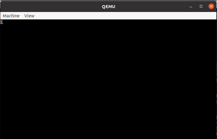
That’s all for our second stage bootloader 😛 I hope you learn something.
See me on Youtube: