Writing Aarch64 bare metal bootloader.
Writing bare metal boot code for Aarch64.
Full source code now is available on this repo: AArch64 Boot Code.
1. Objective
- Understand Aarch64 booting flow, exception levels.
- Using QEMU
virtmachine as a hardware platform. - Booting system from ROM as a bootloader.
- Booting system from RAM as a kernel.
- Self-relocating from ROM to RAM and start executing.
- Able to boot from any Exception Level (EL3->EL0) and changing to lower levels.
- Run the EL0 code in C, and request
svcsystem call to the kernel (EL1 code) and get the result. - Implement a system call dispatcher in EL1.
- Debugging system with GDB.
2. Hardware platform - QEMU
The platform I choose is QEMU, that make us easy to run, debug and able to access by everyone. The machine (SoC) would be virt and the cpu would be cortex-a57.
The virt machine Memory Layout might look like this:
1
2
3
4
5
6
7
8
9
10
11
 _______________ 0x00000000
|     Flash     |
|_______________|0x08000000
|      ...      |
|_______________|0x09000000
|     USART0    |
|_______________|0x09001000
|      ...      |
|_______________|0x40000000
|      RAM      |
|_______________|RAM_LIMIT
- 0..128Mb is space for a flash device, that is used for boot rom code such as UEFI.
- 128MB..256MB is used for device I/O.
- 256MB..1GB is reserved for possible future PCI support.
- 1GB and up is RAM.
Because we are assuming that our application will run as a bare-metal bootloader, the firmware format should be a raw binary image, and should be loaded at a well-known address, that CPU will start at when power up. The QEMU help us to do that by specifying the -bios <firmware> option.
After a reset, the CPU start execute at ROM code 0x00000000, if the -bios <firmware> option is used, QEMU assumes that we are running ROM code, and will load the firmware into Flash memory. The firmware, in this case, have to relocate itself into RAM, and do tasks (like the way UBoot do).
Another choice is using -kernel <firmware> option. Now the QEMU assumes that we are running a kernel, and the bootloader was running before, so it acts like bootloader, loads the firmware directly into RAM and start executing. We can specify our application entry point address in the firmware header, but it should be RAM beginning point, 0x40000000.
So now we have two choices:
- Write ROM code and relocate our application into RAM.
- Write kernel code and let the QEMU loads our application into RAM.
Using
-kernel <firmware>option also has other advantage is that, QEMU acts like a bootloader and able to parse variety kind of kernel image format, for example ELF, PE, or even Linux Kernel format.
We will build 2 versions of firmware, boot.elf that is in ELF format, and can be run as a kernel. And the second boot.bin is ROM boot code version, that has the ability to self-relocate the application into RAM and start executing.
1
2
3
4
5
# Start from ROM (Flash memory).
qemu-system-aarch64 -M virt,virtualization=on,secure=on -cpu cortex-a57 -bios boot.bin -d int -D exceptions.log

# Loaded and start from RAM by QEMU.
qemu-system-aarch64 -M virt,virtualization=on,secure=on -cpu cortex-a57 -kernel boot.elf -d int -D exceptions.log
2.1. Debugging
By using QEMU, we have some advantages for debugging, the bare metal boot code may be harder, but not impossible. let’s discover some ways.
2.1.1. Using GDB
QEMU support using GDB as a remote target, where QEMU will start listen on a port (by default 127.0.0.1:1234) and GDB remote to start debugging. -s option make QEMU listen on that port and -S option make qemu not start the guest until you tell it to start from GDB.
When building the firmware, we should build along with the ELF version, that’s very useful for debugging. We can check symbols and address with aarch64-none-linux-gnu-readelf and also load debug symbol with GDB.
You can run either Aarch64 GDB aarch64-none-linux-gnu-gdb that is provided by ARM or generic version gdb-multiarch. You can specific -ex to exec previous commands, so you don’t have to do this every time. For example, I load the symbol table from boot.elf and remote to QEMU server
1
aarch64-none-linux-gnu-gdb boot.elf -ex "target remote:1234"
NOTE that the symbol address in the binary do not match runtime address. The symbol addresses that you see in ELF file, might not what GDB see. For example, the ELF files define program start at the address 0x40000000, and symbols are based on this address, but when the program running, we DIDN’T load the firmware to address 0x40000000, instead of that we load them to ROM first (0x00000000), and then the code will perform self-relocating to 0x40000000. So when the program is running at ROM, self-relocating code part will not match to the symbol address that GDB see. So you can not set break point with a label, for example b _relocate, GDB will map to it to 0x40000000 from ELF file, but in fact, this code is only be run in case we load the firmware to ROM, so symbol _relocate actually start from 0x00000000. In that case, we have another solution, is that setting break point at a specific address.
For example, let’s say we want to set break point at ROM code copy_loop label. We read ELF file:
1
2
$ ../toolchain/bin/aarch64-none-linux-gnu-readelf boot.elf -s | grep copy_loop
    15: 0000000040000010     0 NOTYPE  LOCAL  DEFAULT    1 copy_loop
This message show that the label copy_loop is located at address 0x0000000040000010. But in fact, we know that this piece of code will run at 0x00000000 instead of 0x40000000. So we have to set break point at address 0x10:
1
2
3
4
5
6
7
8
9
aarch64-none-linux-gnu-gdb boot.elf -ex "target remote:1234"

(gdb) b *0x10
Breakpoint 1 at 0x10
(gdb) c
Continuing.

Breakpoint 1, 0x0000000000000010 in ?? ()
(gdb)
When we perform c -- continue the program will start at our point: 0x0000000000000010.
We will discuss more in the ROM boot - Self Relocating section.
2.1.2. Using QEMU log items
QEMU support logging specific items, using -d <item> option with the item, we want to log:
1
2
3
4
5
6
7
8
9
10
11
12
13
14
15
16
17
18
19
20
21
22
23
24
25
26
Log items (comma separated):
out_asm         show generated host assembly code for each compiled TB
in_asm          show target assembly code for each compiled TB
op              show micro ops for each compiled TB
op_opt          show micro ops after optimization
op_ind          show micro ops before indirect lowering
int             show interrupts/exceptions in short format
exec            show trace before each executed TB (lots of logs)
cpu             show CPU registers before entering a TB (lots of logs)
fpu             include FPU registers in the 'cpu' logging
mmu             log MMU-related activities
pcall           x86 only: show protected mode far calls/returns/exceptions
cpu_reset       show CPU state before CPU resets
unimp           log unimplemented functionality
guest_errors    log when the guest OS does something invalid (eg accessing a
non-existent register)
page            dump pages at beginning of user mode emulation
nochain         do not chain compiled TBs so that "exec" and "cpu" show
complete traces
plugin          output from TCG plugins
strace          log every user-mode syscall, its input, and its result
tid             open a separate log file per thread; filename must contain '%d'
vpu             include VPU registers in the 'cpu' logging
trace:PATTERN   enable trace events

Use "-d trace:help" to get a list of trace events.
You can specify multiple -d options to select multiple kinds of log. Some useful option is -d int that show interrupts and exceptions in short format. We might use it a lot when changing Exception levels. Here is the log we might get:
1
2
3
4
5
6
Exception return from AArch64 EL1 to AArch64 EL0 PC 0x190
Taking exception 2 [SVC] on CPU 0
...from EL0 to EL1
...with ESR 0x15/0x56000001
...with ELR 0x1bc
...to EL1 PC 0x40001400 PSTATE 0x3c5
The log is showing that We just perform jumping from EL1 to EL0 at the PC 0x190 entry point. And then take an exception 2 svc to jump back from EL0 to EL1. The ESR register is Exception syndrome register, that is showing the syndrome information for an exception, because we are in EL1, ESR here refer to ESR_EL1. Similarly, The ELR refer to ELR_EL1 and that is the Exception Link register that hold the address when returning from current exception level. The 0x40001400
Other options like -D help you to redirect these item logs into other output, for example, files -D log.txt.
2.1.3. Logging with virt UART
Unlike the real hardware, maybe need more steps to setup UART, by using QEMU, we can write directly characters into UART Tx by writing to the Tx register. And the log by default will be redirected into stdout. As we know the UART0 peripheral start at memory address 0x09000000, here is the simple macro that I wrote in Aarch64 Assembly to write character directly to Tx register:
1
2
3
4
5
6
7
8
9
10
11
12
13
14
15
16
17
18
19
20
21
22
23
.macro qemu_print reg, len
    sub sp, sp, #24
    str x10, [sp, #0]
    str x11, [sp, #8]
    str x12, [sp, #16]

    mov x10, #0x09000000
    mov x11, #\len
    ldr x12, =\reg
1:
    ldrb w2, [x12] /* Get the first byte and clear all the rest. */
    strb w2, [x10]
    cmp x11, #1
    beq 2f
    sub x11, x11, #1
    add x12, x12, #1
    b 1b
2:
    ldr x12, [sp, #16]
    ldr x11, [sp, #8]
    ldr x10, [sp, #0]
    add sp, sp, #24
.endm
This macro send byte to byte in a loop from the address addr with length len to the Tx register 0x09000000. The ldrb get the first byte in the address that is hold by x12. And here is how we use the qemu_print:
1
2
3
4
qemu_print hello_message, hello_message_len

hello_message: .asciz "Aarch64 bare metal code!\n"
hello_message_len = . - hello_message
it’s easier to write the print function with C:
1
2
3
4
5
6
7
8
9
10
11
12
13
14
volatile unsigned int *const UART0DR = (unsigned int *)0x09000000;
void print_uart0(const char *s)
{
    while (*s != '\0')
    {
        *UART0DR = (unsigned int)(*s);
        s++;
    }
}

void main()
{
    print_uart0("Hello world!\n");
}
But we’re only using C in EL0 for user code.
2.2. Exception level with QEMU
By default, The QEMU assume that you want to emulate kernel code, so the EL default will be 1. To change the EL level to higher, we can specify options virtualization=on, the QEMU assume that we’ll start running at EL2 Hypervisor layer, and with secure=on, QEMU assume that we want to run at EL3 Secure Monitor layer.
In the real hardware, after a reset, the processors will enter EL3 by default. So we will enable both features to emulate real system. The command to start QEMU might look like this:
1
qemu-system-aarch64 -M virt,virtualization=on,secure=on -cpu cortex-a57 -bios boot.bin -d int -D exceptions.log
3. Implementation
3.1. Checking current exception level
When application starts running, first thing we do is check the current EL, in real system, processor will start at EL3, we are using QEMU and able to choose whichever you want, so let’s cover all scenarios.
1
2
3
4
5
6
7
8
9
10
11
12
13
14
15
16
17
18
19
20
21
22
23
24
25
26
27
28
29
30
31
32
33
34
_start:
    /* We don't know current EL yet, so we load a generic stack pointer. */
    ldr x30, =stack_top
    mov sp, x30

    qemu_print hello_message, hello_message_len

    /* Check current EL.*/
    mrs x1, CurrentEL
    cmp x1, 0
    beq in_el0

    cmp x1, 0b0100
    beq in_el1

    cmp x1, 0b1000
    beq in_el2

    cmp x1, 0b1100
    beq in_el3

    b .

in_el3:
    /* EL3 code. */

in_el2:
    /* EL2 code. */

in_el1:
    /* EL1 code. */

in_el0:
    /* EL0 code. */
AArch64 have a special register CurrentEL that hold the current EL value at bit [2:3]:
0b00– EL0.0b01– EL1.0b10– EL2.0b11– EL3.
So we check this register, compare the value and jump to corresponding label.
3.2. Stack pointer
Each exception level has its own stack pointer. When you are in ELx, the sp refer to actual register SP_ELx. So you should create a stack frame for each EL, big enough, at least enough for handling exceptions. I have spent 0x1000 for each stack, and define them in the linker script file:
1
2
3
4
5
6
7
8
9
10
11
12
13
14
15
16
17
18
19
20
21
SECTIONS
{
 . = 0x40000000;
 .start : {head.o (.text)}
 .text : { *(.text) }
 .rodata : { *(.rodata) }
 .data : { *(.data) }
 _end_copy_image = .;
 .bss : { *(.bss COMMON) }
 . = ALIGN(8);
 . = . + 0x1000;
 el3_stack_top = .;
 . = . + 0x1000;
 el2_stack_top = .;
 . = . + 0x1000;
 el1_stack_top = .;
 . = . + 0x1000;
 el0_stack_top = .;
 stack_top = .;
 . = ALIGN(8);
}
You can only use the name
SP_ELxto access stack pointer of lower exception level. For example, if you are in EL2, you only can access toSP_EL1,SP_EL0, you can not useSP_EL3due to the permission, and theSP_EL2due to you are in EL2, andspis actually refer toSP_EL2, try to access might cause an exception.
3.3. Entering lower exception level code
The processor only change the exception levels when an exception is taken or returned. So if the processor start with an higher level and we want to enter lower, we have to use a fake exception return. These steps are:
- Initialize execution state and control registers.
- Executing
eretinstruction.
There are two special registers used to return from an exception:
SPSR_ELx– Saved Program Status Register – This register holds the saved process state when an exception is taken into correspondingELxlevel.ELR_ELx– Exception Link Register – when taking an exception to ELx, holds the address to return to.
Normally, these registers are saved automatically by hardware when entering an exceptions, but in our case, we want to change from higher to lower level, we have to configure them manually. And when we call the eret instruction, hardware will read these registers and restore the CPU state.
3.3.1. EL3 to EL2
If our application starts running at EL3, the CPU will jump to this piece of code in_el3, this is where we need to set up the execution state to return to EL2.
in_el3:
    /* Secure monitor code. */
    ldr x1, =el3_stack_top
    mov sp, x1
    qemu_print in_el3_message, in_el3_message_len

    ldr x1, =vector_table_el3       /* Load EL3 vector table.                 */
    msr vbar_el3, x1

    /* Set up Execution state before return to EL2. */
    msr sctlr_el2, xzr      /* Clear System Control Register.                 */
    msr hcr_el2, xzr        /* Clear the Hypervisor Control Register.         */

    mrs x0, scr_el3         /* Configure Secure Control Register:             */
    orr x0, x0, #(1<<10)    /* EL2 exception state is AArch64.                */
    orr x0, x0, #(1<<0)     /* Non Secure state for EL1.                      */
    msr scr_el3, x0

    mov x0, #0b000001001    /* DAIF[8:5]=0000 M[4:0]=01001 EL0 state:         */
    msr spsr_el3, x0        /* Select EL2 with SP_EL2.                        */

    adr x0, in_el2
    msr elr_el3, x0
    eret

in_el2:
    /* EL2 code. */
Because We do not use secure feature, so we disable the Security state of EL2 and lower. we do that by setting NS, bit[0] in scr_el3 – Secure configuration register. Bits[4:0] in register spsr_el3, decided Exception Level and selected Stack pointer, we configure value 0b1001 indicate the state will return is in EL2 with SP_EL2 (EL2h). Finally, we load the in_el2 relative address into elr_el3 and call eret to return to EL2.
3.3.2. EL2 to EL1
Even if processor starts at EL3, we changed from EL3 to EL2, or starts at EL2, the EL2 code will start from here:
1
2
3
4
5
6
7
8
9
10
11
12
13
14
15
16
17
18
19
20
21
22
23
24
25
in_el2:
    ldr x1, =el2_stack_top
    mov sp, x1
    qemu_print in_el2_message, in_el2_message_len

    ldr x1, =vector_table_el2       /* Load EL2 vector table.                 */
    msr vbar_el2, x1

    /* Set up Execution state before return to EL1. */
    msr sctlr_el1, xzr      /* Clear System Control Register.                 */

    mrs x0, hcr_el2         /* Set bit 31th: RW the Execution state for EL1.  */
    orr x0, x0, #(1<<31)
    msr hcr_el2, x0

    mov x0, #0b000000101    /* DAIF[8:5]=0000 M[4:0]=00101 The state indicate */
    msr spsr_el2, X0        /* EL1 with SP_EL1.                               */

    adr x0, in_el1
    msr elr_el2, x0

    eret

in_el1:
    /* EL1 code. */
Similar to changing EL3 to EL2, we set up the Execution state before return to EL1. We also need to configure the Execution state for EL1 is AArch64 by setting bit[31] in hcr_el2.
3.3.3. EL1 to EL0
1
2
3
4
5
6
7
8
9
10
11
12
13
14
15
16
17
18
19
20
21
22
in_el1:
    ldr x1, =el1_stack_top
    mov sp, x1
    qemu_print in_el1_message, in_el1_message_len

    /* Set up Execution state before return to EL0. */
    ldr x1, =vector_table_el1
    msr vbar_el1, x1

    mov x0, #0b000000000    /* DAIF[8:5]=0000 M[4:0]=00000 EL0 state.         */
    msr spsr_el1, x0

    adr x0, in_el0
    msr elr_el1, x0
    eret

in_el0:
    ldr x1, =el0_stack_top
    mov sp, x1
    qemu_print in_el0_message, in_el0_message_len
    bl el0_main
    b .
The EL1 do the same steps to change into EL0. And now we are in the EL0, I want to change to C code a bit because Assembly is so boring 😛. The el0_main is written in C:
1
2
3
4
5
6
7
8
9
10
11
12
13
14
15
16
17
18
19
20
21
22
23
24
void el0_main()
{
    u64 result = 0;
    print_uart0("Enter el0_main!\n");

    /* 1. Request the syscall. */
    asm("mov x0, #1;" /* x0 -- holds the first parameter.   */
        "mov x1, #2;" /* x1 -- holds the second parameter.  */
        "mov x8, #4;" /* x8 -- holds the syscall number.    */
        "svc #0");

    /* 2. Get the syscall result. */
    asm("mov x0,%0" : "=r"(result));
    if (result != 3)
    {
        print_uart0("System call return a incorrect result.\n");
    }
    else
    {
        print_uart0("System call return a correct result.\n");
    }

    print_uart0("Exit el0_main!\n");
}
The user code do nothing but call a system call to request service from EL1, that we’ll discuss more in next sections.
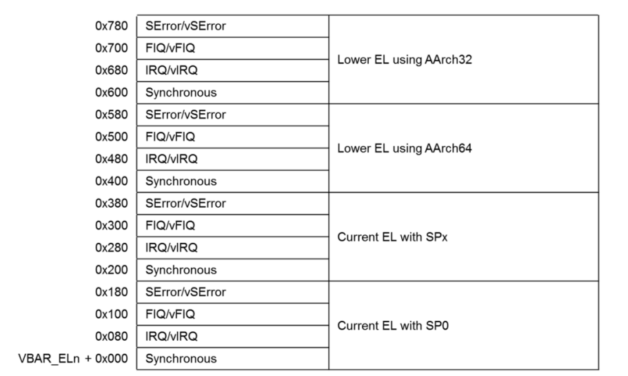
3.4. Vector tables
Unlike Cortex-M vector table, where we have only one table at fixed-location memory. On Cortex-A, we have vector table for each EL, and of course, the memory is flexible (but must be placed at a 2KB-aligned address). The addresses are specified by initializing VBAR_ELx registers, as you can see I did for all EL code before.
There are 16 entries for each table, each entry is 128B in size and contains at most 32 instructions.
Here is how we make the table in assembly:
1
2
3
4
5
6
7
8
9
10
11
12
13
14
15
16
17
18
19
20
21
22
23
24
25
26
27
28
29
30
31
32
33
34
35
36
37
38
39
40
41
42
43
44
45
46
47
48
49
50
.text
.balign 0x800
vector_table_el1:
el1_curr_el_sp0_sync:
    b .
.balign 0x80
el1_curr_el_sp0_irq:
    b .
.balign 0x80
el1_curr_el_sp0_fiq:
    b .
.balign 0x80
el1_curr_el_sp0_serror:
    b .
.balign 0x80
el1_curr_el_sp1_sync:
    b .
.balign 0x80
el1_curr_el_sp1_irq:
    b .
.balign 0x80
el1_curr_el_sp1_fiq:
    b .
.balign 0x80
el1_curr_el_sp1_serror:
    b .
.balign 0x80
el1_lower_el_aarch64_sync:
    b el1_lower_el_aarch64_sync_handler
.balign 0x80
el1_lower_el_aarch64_irq:
    b .
.balign 0x80
el1_lower_el_aarch64_fiq:
    b .
.balign 0x80
el1_lower_el_aarch64_serror:
    b .
.balign 0x80
el1_lower_el_aarch32_sync:
    b .
.balign 0x80
el1_lower_el_aarch32_irq:
    b .
.balign 0x80
el1_lower_el_aarch32_fiq:
    b .
.balign 0x80
el1_lower_el_aarch32_serror:
    b .
Load the EL1 vector table address into vbar_el1.
1
2
3
4
5
in_el1:
    /* ... */
    ldr x1, =vector_table_el1
    msr vbar_el1, x1
    /* ... */
I’m currently not handling other exceptions except the exception from lower EL using AArch64 el1_lower_el_aarch64_sync_handler that is mainly used to handle svc command from EL0, we will discuss more in the next section. We branch into el1_lower_el_aarch64_sync_handler to handle this one, for others, I use b . to loop forever, it means I haven’t implemented yet 😛.
3.5. System calls
System calls are the way lower level code request for higher level code services. We have four ELs so we have three system call instructions to request upper services:
svc– EL0 request to EL1.hvc– EL1 request to EL2.smc– Lower (EL1, EL2) to EL3.
These instructions trigger an synchronous exception to upper level, and the return address indicates the instruction that caused it. There are some registers supply the key information for handling of sync exceptions, as well as SErrors:
ESR_ELx– Exception syndrome register – provides information about the cause and type of sync exception.FAR_ELx– Fault address register – holds the faulting virtual address for address-related sync exceptions, such as MMU fault.ELR_ELx– Exception link register – holds the address of the triggering instruction, providing the return address for the exception.
In this project, I will demonstrate by implementing an svc handler, to handle request from EL0 to EL1.
3.5.1. SVC exception handling
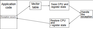
Triggering svc instruction following these steps:
- Hardware: Current state
PSTATEis preserved as a snapshot inSPSR_EL1. - Hardware: Exception return address is written to
ESR_EL1. PSTATEis updated, with EL changed to EL1.ESR_ELxis updated to indicate a type of sync exception.- Hardware: CPU branch to the vector table (pointed to by
VBAR_EL1) at offset0x400(Synchronous - Lower EL using Aarch64). - Software: Registers are stacked to maintain register context.
- Software: Specific SVC code is then executed.
- Software: Restore all previous stacked registers and executes and
ERETinstruction. - Hardware:
PSTATEis restored fromSPSR_EL1and thepcis updated to the value contained inELR_EL1.
There are some steps are done by the hardware, our jobs, as the software is save the context, handle SVC request, and restore the context before exiting.
3.5.2. Saving/Restoring current state
There are 31 registers that determine the current context, x0..x30. We save them as a trap frame before handling the exception, and restore them before exiting back to the previous context. As I mentioned about the stack before, in that case SP_EL1, it should be big enough to save the trap frame and handle specific exceptions (I have met a stack corruption issue, and it was so painful to debug 😭).
1
2
3
4
5
6
7
8
9
10
11
12
13
14
15
16
17
18
19
20
21
22
23
24
25
26
27
28
29
30
31
32
33
34
35
36
37
38
39
40
41
42
43
44
45
46
47
48
.macro save_trap_frame el
    stp x29, x30, [sp, #-16]!
    stp x27, x28, [sp, #-16]!
    stp x25, x26, [sp, #-16]!
    stp x23, x24, [sp, #-16]!
    stp x21, x22, [sp, #-16]!
    stp x19, x20, [sp, #-16]!
    stp x17, x18, [sp, #-16]!
    stp x15, x16, [sp, #-16]!
    stp x13, x14, [sp, #-16]!
    stp x11, x12, [sp, #-16]!
    stp x9, x10, [sp, #-16]!
    stp x7, x8, [sp, #-16]!
    stp x5, x6, [sp, #-16]!
    stp x3, x4, [sp, #-16]!
    stp x1, x2, [sp, #-16]!

    mrs x21, spsr_\el
    stp x21, x0, [sp, #-16]!
.endm

.macro restore_trap_frame el
    ldp x21, x0, [sp], #16
    msr spsr_\el, x21
    ldp x1, x2, [sp], #16
    ldp x3, x4, [sp], #16
    ldp x5, x6, [sp], #16
    ldp x7, x8, [sp], #16
    ldp x9, x10, [sp], #16
    ldp x11, x12, [sp], #16
    ldp x13, x14, [sp], #16
    ldp x15, x16, [sp], #16
    ldp x17, x18, [sp], #16
    ldp x19, x20, [sp], #16
    ldp x21, x22, [sp], #16
    ldp x23, x24, [sp], #16
    ldp x25, x26, [sp], #16
    ldp x27, x28, [sp], #16
    ldp x29, x30, [sp], #16
.endm

el1_lower_el_aarch64_sync_handler:
    save_trap_frame el1
    mov x0, sp
    mrs x1, esr_el1
    bl el1_sync_handler
    restore_trap_frame el1
    eret
To handle the exception, I jumped into el1_sync_handler in C, and pass the trap_frame pointer and esr_el1 parameters along with that.
1
2
3
4
5
6
7
8
9
10
11
12
13
14
#define SVC_AARCH64 0b010101
#define GET_EC_BITS(reg) (((reg >> 26) << 32) >> 32)

void el1_sync_handler(trap_frame_t *trap_frame, u64 esr_el1)
{
    /* 1. Parse the Exception Class bits[31:26] in ESR_EL1. */
    if (GET_EC_BITS(esr_el1) == SVC_AARCH64)
    {
        svc_handler(trap_frame);
    }
    else
    { // Not implemented yet.
    }
}
The reason esr_el1 is needed is that, it provides us information about the exception, in that case, bits[31:26] tell us about the Exception Class. For now, we capture and handle the SVC exception only.
3.5.3. Kernel system call dispatcher
There is only one instruction svc to request services from EL0 to EL1. But, there are so many resources EL0 need to access. For example, an application maybe want to read/write to a file on the hard disk, but also wants to connect to a HTTP server via the Internet. To indicate which service EL0 want to do, we use well-known numbers called as system call numbers. The Kernel (EL1) maintains a table to dispatch from the number to corresponding system call handler.
There are several ways to pass the number when calling a svc:
- Using svc number, that is passed when calling the
svcinstruction. For example,svc #4, indicates EL0 want to request service 4 in EL1. There are some limits to this approach, for example the number is limited from 0-255. - Using general registers as request’s parameters.
The Second approach is the most popular, Linux is an example, that using x8 to hold the system call number and x0..x7 as argument registers. The system call result is saved into x0. We will use it as a standard, so in the svc_handler we implement a simple dispatcher like this:
1
2
3
4
5
6
7
8
9
10
11
12
13
14
15
16
17
18
19
20
21
22
23
#define ADD_SYSCALL_NUMBER 4
#define MAX_SYSCALL 10

typedef void (*syscall)(trap_frame_t *trap_frame);

const syscall syscalls[MAX_SYSCALL] = {
    /* ... */
    [ADD_SYSCALL_NUMBER] = add_syscall_handler,
    /* ... */
};

void svc_handler(trap_frame_t *trap_frame)
{
    /* 1. Validate system call number. */
    if (trap_frame->x8 >= MAX_SYSCALL || syscalls[trap_frame->x8] == NULL)
    {
        print_uart0("Invalid syscall number!\n");
        return;
    }

    /* 2. Call corresponding system call. */
    syscalls[trap_frame->x8](trap_frame);
}
First we validate the system call number that is stored in x8, and then we call the corresponding system call handler that is hold by the system call table syscalls.
3.5.4. Request a system call from user
To call the svc instruction, we have to use inline assembly, and before that we have to setup other registers. The x0 holds the first parameter, the x1 holds the second parameter, and the x8 holds the system call number.
1
2
3
4
5
6
7
8
9
10
11
12
13
14
15
16
17
18
19
20
21
22
23
24
void el0_main()
{
    u64 result = 0;
    print_uart0("Enter el0_main!\n");

    /* 1. Request the syscall. */
    asm("mov x0, #1;" /* x0 -- holds the first parameter.   */
        "mov x1, #2;" /* x1 -- holds the second parameter.  */
        "mov x8, #4;" /* x8 -- holds the syscall number.    */
        "svc #0");

    /* 2. Get the syscall result. */
    asm("mov x0,%0" : "=r"(result));
    if (result != 3)
    {
        print_uart0("System call return a incorrect result.\n");
    }
    else
    {
        print_uart0("System call return a correct result.\n");
    }

    print_uart0("Exit el0_main!\n");
}
In this example, we are assuming that, we use system call number 4 for add service, that means we add two arguments and return the result.
1
2
3
4
5
6
7
8
9
10
11
12
13
14
15
#define ADD_SYSCALL_NUMBER 4
#define MAX_SYSCALL 10

typedef void (*syscall)(trap_frame_t *trap_frame);

const syscall syscalls[MAX_SYSCALL] = {
    /* ... */
    [ADD_SYSCALL_NUMBER] = add_syscall_handler,
    /* ... */
};

void add_syscall_handler(trap_frame_t *trap_frame)
{ // This syscall add two parameters and return the result.
    trap_frame->x0 = trap_frame->x0 + trap_frame->x1;
}
The result will be saved into x0, that is where the user code can get.
1
    asm("mov x0,%0" : "=r"(result));
4. ROM code and self-relocating
Now assume that our firmware is flashed to ROM memory (start from 0x00000000) as a bootloader, there is no loader running before to parse the firmware format like ELF, etc. So firmware format should be raw binary and .text section must be first. The _relocate code copy the the firmware itself from 0x00000000 to _end_copy_image symbol and place to RAM 0x40000000. And then jump to the RAM code and start executing.
1
2
3
4
5
6
7
8
9
10
11
12
13
14
15
16
17
18
19
20
21
22
23
24
25
26
27
28
29
30
31
.text
.globl _start

/* If the firmware is run as ROM code, QEMU have no idea about the entry point.
 * So the CPU will start execute from 0x00000000, we perform relocating our
 * application to RAM. */
_relocate:
    mov x0, 0x00
    ldr x1, =_end_copy_image
    mov x2, #0x40000000
    sub x1, x1, x2

    // x0 holds start, x2 holds destination and x1 holds the copy size.
copy_loop:
    ldr x3, [x0]
    str x3, [x2]

    add x2, x2, #4
    add x0, x0, #4
    sub x1, x1, #4
    cmp x1, #0
    bne copy_loop

    /* After loading, we jump into the application entry point on RAM. */
    ldr x1, =_start
    br x1

/* Here is actually our application entry point, if the firmware is run as
 * kernel. QEMU will read the entry point from ELF file, and jump directly to
 * this address, ignore _relocate code. */
_start:
Note that 2 symbols _end_copy_image, _start are replaced with values by the linker when linking, and the linker parse this the linker script, relocate and get the values. The point is, Linker script are assumed to run our firmware on RAM (start from 0x40000000), so the value of _end_copy_image will be 0x40000000 + .text size + .rodata size + .data. And the _start value is calculated from 0x40000000 + _start label symbol.
1
2
3
4
5
6
7
8
9
10
11
12
13
14
15
16
17
18
19
20
21
SECTIONS
{
 . = 0x40000000;
 .start : {head.o (.text)}
 .text : { *(.text) }
 .rodata : { *(.rodata) }
 .data : { *(.data) }
 _end_copy_image = .;
 .bss : { *(.bss COMMON) }
 . = ALIGN(8);
 . = . + 0x1000;
 el3_stack_top = .;
 . = . + 0x1000;
 el2_stack_top = .;
 . = . + 0x1000;
 el1_stack_top = .;
 . = . + 0x1000;
 el0_stack_top = .;
 stack_top = .;
 . = ALIGN(8);
}
So what I do here to get the image size is minus the _end_copy_image for 0x40000000. And we copy the image size to RAM. Note that, we don’t have to copy .bss section because there is no meaningful data in there.
5. Testing system
Start CPU execution at EL3:
1
2
3
4
5
6
7
8
9
$ qemu-system-aarch64 -M virt,virtualization=on,secure=on -cpu cortex-a57 -nographic -kernel boot.elf -D log.txt -d int
Aarch64 bare metal code!
In EL3!
In EL2!
In EL1!
In EL0!
Enter el0_main!
System call return a correct result.
Exit el0_main!
Start CPU execution at EL2:
1
2
3
4
5
6
7
8
$ qemu-system-aarch64 -M virt,virtualization=on,secure=off -cpu cortex-a57 -nographic -kernel boot.elf -D log.txt -d int
Aarch64 bare metal code!
In EL2!
In EL1!
In EL0!
Enter el0_main!
System call return a correct result.
Exit el0_main!
Start CPU execution at EL1:
1
2
3
4
5
6
7
$ qemu-system-aarch64 -M virt,virtualization=off,secure=off -cpu cortex-a57 -nographic -kernel boot.elf -D log.txt -d int
Aarch64 bare metal code!
In EL1!
In EL0!
Enter el0_main!
System call return a correct result.
Exit el0_main!
Load firmware as a ROM boot code and do self-relocate:
1
2
3
4
5
6
7
8
$ qemu-system-aarch64 -M virt,virtualization=on,secure=off -cpu cortex-a57 -nographic -bios boot.bin -D log.txt -d int
Aarch64 bare metal code!
In EL2!
In EL1!
In EL0!
Enter el0_main!
System call return a correct result.
Exit el0_main!
That’s it for this blog, I hope you learn something, if you want me to learn more about other stuff, don’t be shy message to me 😛.